Gas Circuit Breaker (GCB) - Continue


Current interruption in a high-voltage circuit-breaker is obtained by separating two contacts in a medium, such as SF6, having excellent dielectric and arc quenching properties. After contact separation, current is carried through an arc and is interrupted
when this arc is cooled by a gas blast of sufficient intensity. Gas blast applied on the arc must be able to cool it rapidly so that gas temperature between the contacts is reduced from 20,000 K to less than 2000 K in a few hundred microseconds, so that it is able to withstand the transient recovery voltage that is applied across the contacts after current interruption. SF6 is generally used in present high-voltage circuit-breakers.

Interrupting Phenomena

 SF6 gas in the cylinder is compressed by the downward movement
 Gas is forced into the nozzle where the arc is drawn.
 In early stages pressure inside the cylinder is raised.
 Nozzle concentrates the gas flow to the area of the arc.


Parameter Definition

Rated Voltage
The maximum voltage at which a circuit breaker can operate for extended periods without undue degradation or safety hazard.

Rated Short Circuit breaking Current
The highest electric current which can exist in a particular electrical system under short circuit conditions.

Rated Operating Sequence
This denotes the sequence of opening and closing operations which the circuit breaker can perform under specified conditions. The circuit breaker should be able to perform the
operating sequence as follows:

O-t-CO-T-CO

Where, O = opening operation
t = time required to be ready to receive closing order from auto- reclosure relay
CO = close operation followed by open operations
T = time required to insulating media for regeneration and operating mechanism

Rated Lightning Impulse Withstand Voltage
Lightning impulse voltage rating which the gas circuit breaker can withstand.

Rated Short Duration Power-Frequency Withstand Voltage
R.M.S. value of sinusoidal power frequency voltage that the breaker can withstand during tests made under specified conditions and for a specified time.
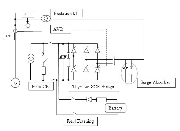
AVR Automatic Voltage Regulator


Generator Control
Automatic Voltage Regulator (AVR) is the main controller of the Generator.AVR has the control over the Excitation System.

Voltage Regulator
The voltage regulator are composed of automatic voltage regulator(AVR), manual voltage
regulator (MEC) and over current limiter(OCL).

Automatic voltage regulator (AVR)
An automatic voltage control device "senses" changes in output voltage and causes a
change in field resistance to keep output voltage constant. The AVR is capable of covering
80% to 110% of the rated voltage of the generator at no-load operation.

AVR- Function

AVR required -Terminal Voltage, Current and Phase Angle as its inputs. By the use of these inputs it controls the firing angle of the thyristor bank, Not only that when Electric brake is applied, there will be a huge current drowning from the generator which may damage the stator winding and to avoid that field current will be reduced to keep only the rated current in the stator.

Manual voltage regulator (MEC)
In case of AVR trouble, the voltage control system is set automatically from “automatic”
(AVR) to “manual” (MEC). To trail charge the transmission line, the generator voltage is
controlled stable from 30% of the rated voltage to the full voltage using MEC.

Over Current Limiter (OCL)
An OCL automatically limit the generator stator current within a rated current by raising
the power factor of generator up to 1.0, when the generator current increases over 101% of
the rated current due to drop of generator voltage.

Applications of AVR
1. Voltage control at no load operation before synchronizing
2. Reactive Power output control after synchronizing
3. Isolated operation
4. Line charging


Excitation System

Excitation System provides field current to the rotor which produces the magnetic flux of the generator.
Main types of Exciters:
• Slip rings link the rotor’s field winding to an external dc source
• DC generator exciter(Shaft mounted)
• Brushless exciter

Input Power Source for Static Exciter
1. Self –excited shunt system
2. Self-excited compound system
3. Separately –excited station power source system
4. Separately-excited brushless generator system


The self-excited shunt system has been adopted in a great number of hydro power plants for its inexpensive cost and easy maintenance. Based on the studies, the static system is recommended as follows:
a. Input power source for static exciter is self-excited shunt system
b. Connection scheme of thyristor is applied to be the full bridge system

In case of self-excited shunt system is applied, an initial excitation power source must be separately provided to build-up the generator voltage up to a certain voltage at which AVR and thyristor gate circuits are adequately activated.

SURGE ARRESTER- Introduction


SURGE ARRESTER

Surge arrester is a device used to protect equipments against over voltages. MOS (Metal Oxide Surge Arrester) - Without gaps will be used in UKHP. It consists of ZnO element which has excellent non-linear voltage-current characteristic.

MAIN CAUSES OF OVER VOLTAGES

1. Lightning Surges - 8/20 current impulses.

2. Switching Surges - has a peak value of discharge current having a virtual front time greater than 30 μs but less than 100 μs and a virtual time to half-value on the tail of roughly twice the virtual front time.

3. Temporary over voltages - by line-to-ground faults, load rejection & continued for a few milliseconds to a few seconds.

Nominal discharge current - of an arrester is the peak value of lightning current impulse which is used to classify an arrester.


Gas Circuit Breaker (GCB)

Gas Circuit Breaker (GCB)

Current interruption in a high-voltage circuit-breaker is obtained by separating two contacts in a medium, such as SF6, having excellent dielectric and arc quenching properties. After contact separation, current is carried through an arc and is interrupted when this arc is cooled by a gas blast of sufficient intensity. Gas blast applied on the arc must be able to cool it rapidly so that gas temperature between the contacts is reduced from 20,000 K to less than 2000 K in a few hundred microseconds, so that it is able to withstand the transient recovery voltage that is applied across the contacts after current interruption. SF6 is generally used in present high-voltage circuit-breakers.

Circuit breaker

Circuit breaker

The circuit breaker is used for switching the circuit current and short circuit current interruption. There are two types of circuit breakers used in power station.

1. Live tank type: Enclosure-Live, Breaking parts-Live
2. Dead tank type: Enclosure-Grounded, Breaking parts-Live

For arc Interruption in a circuit breaker Air, Oil, Vacuum, Gas (SF6) are used.

Substation types


Air Insulated Switchgear

An electric power substation that has the bus bars and equipment terminations generally
open to air and utilizes insulation properties of ambient air for insulation to ground.


Gas Insulated Switchgear

An electric power substation in which all live equipment and bus bars are housed in grounded metal enclosures sealed and filled with sulfur hexafluoride gas. An effective although more costly form of switchgear is "gas insulated switchgear" (GIS), conductors and contacts are insulated by pressurized (SF6) sulfur hexafluoride gas. Advantage of GIS comparing to conventional air insulated substation are space saving, high reliability and easy maintenance.

SWITCHYARD EQUIPMENT- Introduction

Substation

An electrical substation is a subsidiary station of an electricity generation, transmission and distribution system where voltage is transformed from high to low or the reverse using transformers. Electric power may flow through several substations between generating plant and consumer, and may be changed in voltage in several steps.

Conservator System

The conservator contains an expandable bladder or diaphragm between the oil and air. Air enters and exits the space above the bladder/diaphragm as the oil level in the main tank goes up and down with temperature.