Showing posts with label Generator. Show all posts

AVR Automatic Voltage Regulator


Generator Control
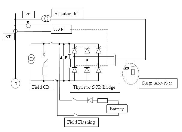
Automatic Voltage Regulator (AVR) is the main controller of the Generator.AVR has the control over the Excitation System.

Voltage Regulator
The voltage regulator are composed of automatic voltage regulator(AVR), manual voltage
regulator (MEC) and over current limiter(OCL).

Automatic voltage regulator (AVR)
An automatic voltage control device "senses" changes in output voltage and causes a
change in field resistance to keep output voltage constant. The AVR is capable of covering
80% to 110% of the rated voltage of the generator at no-load operation.

AVR- Function

AVR required -Terminal Voltage, Current and Phase Angle as its inputs. By the use of these inputs it controls the firing angle of the thyristor bank, Not only that when Electric brake is applied, there will be a huge current drowning from the generator which may damage the stator winding and to avoid that field current will be reduced to keep only the rated current in the stator.

Manual voltage regulator (MEC)
In case of AVR trouble, the voltage control system is set automatically from “automatic”
(AVR) to “manual” (MEC). To trail charge the transmission line, the generator voltage is
controlled stable from 30% of the rated voltage to the full voltage using MEC.

Over Current Limiter (OCL)
An OCL automatically limit the generator stator current within a rated current by raising
the power factor of generator up to 1.0, when the generator current increases over 101% of
the rated current due to drop of generator voltage.

Applications of AVR
1. Voltage control at no load operation before synchronizing
2. Reactive Power output control after synchronizing
3. Isolated operation
4. Line charging


Excitation System

Excitation System provides field current to the rotor which produces the magnetic flux of the generator.
Main types of Exciters:
• Slip rings link the rotor’s field winding to an external dc source
• DC generator exciter(Shaft mounted)
• Brushless exciter

Input Power Source for Static Exciter
1. Self –excited shunt system
2. Self-excited compound system
3. Separately –excited station power source system
4. Separately-excited brushless generator system


The self-excited shunt system has been adopted in a great number of hydro power plants for its inexpensive cost and easy maintenance. Based on the studies, the static system is recommended as follows:
a. Input power source for static exciter is self-excited shunt system
b. Connection scheme of thyristor is applied to be the full bridge system

In case of self-excited shunt system is applied, an initial excitation power source must be separately provided to build-up the generator voltage up to a certain voltage at which AVR and thyristor gate circuits are adequately activated.

Damper winding

Damper winding
A continuous cage type damper winding is provided to improve stability and specially to reduce higher harmonic voltages under conditions of unbalanced faults. The winding has low resistance and rigid construction, and is designed to have the specified characteristics.

Generator Operation Modes

Generator Operation Modes

There are three operating methods of a Hydro Generator for different states.

• Generation Mode

• Line Charge Mode

• Total Blackout Mode

Generation mode is applied when it is only required to generate power in absolute normal conditions.

Line charge mode is applied when it is required to charge the line from Power Station to the Grid Substation.

Total Blackout mode is used when there is a total black out in whole country.

Power System Stabilizer (PSS)

Power System Stabilizer (PSS)
A PSS of the accelerating power deviation or power sensor type is provided for increasing
both damping and synchronizing torque of power system and for eliminating shaft torsion.

Voltage Regulators

Voltage Regulator
The voltage regulator are composed of automatic voltage regulator(AVR), manual voltage regulator (MEC) and over current limiter(OCL)

Automatic voltage regulator (AVR)
An automatic voltage control device "senses" changes in output voltage and causes a change in field resistance to keep output voltage constant. The AVR is capable of covering 80% to 110% of the rated voltage of the generator at no-load operation.

Manual voltage regulator (MEC)
In case of AVR trouble, the voltage control system is set automatically from “automatic” (AVR) to “manual” (MEC). To trail charge the transmission line, the generator voltage is controlled stable from 30% of the rated voltage to the full voltage using MEC.

Maximum Generator Voltage Rise

Maximum Generator Voltage Rise
The exciter is capable of depressing the voltage rise of the generator within 15% of rated voltage under the conditions that the field breaker is in closed position and the speed rise of generator within 55% of rated speed when full load of generator is rejected due to outside faults.

Excitation Systems

Main Types of Excitation Systems

1. Self –excited shunt system
2. Self-excited compound system
3. Separately –excited station power source system
4. Separately-excited brushless generator system

The self-excited shunt system has been adopted in a great number of hydro power plants for its inexpensive cost and easy maintenance. Based on the studies, the static system is recommended as follows:
a. Input power source for static exciter is self-excited shunt system
b. Connection scheme of thyristor is applied to be the full bridge system

In case of self-excited shunt system is applied, an initial excitation power source must be separately provided to build-up the generator voltage up to a certain voltage at which AVR and thyristor gate circuits are adequately activated.

More detail on Excitation Systems

Generator main shaft

Generator main shaft
The generator main shaft is made of forged carbon steel property heat treated according to ASTM A668/A668M-02 class D, E or JIS G3201. The alignment of the shaft is checked with rotation. The first critical speed of is not less than 130% of the runaway speed of the turbine.The Generator Sharft is connect to Turbine main shaft. There are two ways of doing it.
1.Directly couple.
2.Through a Gear System.

Generator Voltage Control at Transmission Line Charging

Transmission Line Charging
To initially charge the transmission line, the generator voltage stably controlled from 30% of the rated voltage to 110% of the rated voltage by using AVR. The change-over switch (43CH) for initial transmission line charging is mounted on the operator’s desk in the main control room.This Voltage Changes are required because of the Stray capacitance effect at the charging and boosts the Voltage at the other end and the inductance of the line drops the Voltage soon after charging.

Dielectric Strength

Dielectric Strength of windings is a main parameter of a Hydro Generator.The generator winding should safely withstand the following power frequency test voltages for one minute in accordance with IEC 60034-1. Normally Stator winding 28600V Rotor winding ten times the rated excitation voltage with minimum of 1500V.This Dielectric property decides the Insulation Class and the size of the machine.

Generator stator winding-Mechanical Stength

Mechanical Strength
The generator is designed to safely withstand rush-current flowing during sudden three phase or single phase short-circuits at the terminal ends of the generator under full load generating conditions without any deformations in the stator windings or rotor or any other injury.

Generator Windings- Temperature limits

The temperature rise in stator winding when operating continuously under the rated conditions is not more than 85c. Temperature of the stator winding is measured by embedded RTD. The temperature rise in rotor winding when operating continuously under the rated conditions is not more than 85c. Temperature of the stator winding is measured by resistance method. Outlet temperature from surface air cooler is not more than 400 C.

Cooling system of a Hydro Generator

The cooling medium is air which is drawn through channels in the stator core and rotor steels. Heat generated by current flowing in the windings must travel via thermal conduction through the electrical insulation and through the surrounding steel to the cooling medium. Cooling system of each generator has a sufficient capacity to operate the generator at the rated output without exceeding specific temperature rise. Air is circulated by fan action of rotor spider, rotor rim and field poles. It is called rim-duct air circulation. Further air circulates through the open parts of stator frame and coolers.

The Stator of a Hydro Generator

Stator consists of Stator Frame, Stator Core, and Stator Winding. Stator Core Consists thin steel sheet lamination. The stator winding is made of copper, and shall be of sufficiently transposed one turn coil placed in double layer in each slot having uniform shape and dimensions, and is replaceable and exchangeable.

Stator core is built from thin laminations to minimize the transformer type electrical losses and of specially rolled silicon steel to minimize hysteresis losses. The inner diameters of laminations have slots running the entire axial length of the core for stator coils. These slots extend into each punching deeply enough to contain the stator winding. The portion of the core between the slots is termed the teeth area. In Upper Kotmale, laminations are punched as arcs of a circle and then assembled into the finished circular stator core. Stator core is made by Non-oriented magnetic steel sheet. Stator core class is 50A350. Stator core class: 50 A 350

Standard Type

Use for high speed (170 -1000rmp)

Top mounted thrust & guide bearing supported on a heavy bracket

The most expensive generator design

Small rotor diameter