Generator Control
Automatic Voltage Regulator (AVR) is the main controller of the Generator.AVR has the control over the Excitation System.
Voltage Regulator
The voltage regulator are composed of automatic voltage regulator(AVR), manual voltage
regulator (MEC) and over current limiter(OCL).
Automatic voltage regulator (AVR)
An automatic voltage control device "senses" changes in output voltage and causes a
change in field resistance to keep output voltage constant. The AVR is capable of covering
80% to 110% of the rated voltage of the generator at no-load operation.
AVR- Function
AVR required -Terminal Voltage, Current and Phase Angle as its inputs. By the use of these inputs it controls the firing angle of the thyristor bank, Not only that when Electric brake is applied, there will be a huge current drowning from the generator which may damage the stator winding and to avoid that field current will be reduced to keep only the rated current in the stator.
Manual voltage regulator (MEC)
In case of AVR trouble, the voltage control system is set automatically from “automatic”
(AVR) to “manual” (MEC). To trail charge the transmission line, the generator voltage is
controlled stable from 30% of the rated voltage to the full voltage using MEC.
Over Current Limiter (OCL)
An OCL automatically limit the generator stator current within a rated current by raising
the power factor of generator up to 1.0, when the generator current increases over 101% of
the rated current due to drop of generator voltage.
Applications of AVR
1. Voltage control at no load operation before synchronizing
2. Reactive Power output control after synchronizing
3. Isolated operation
4. Line charging
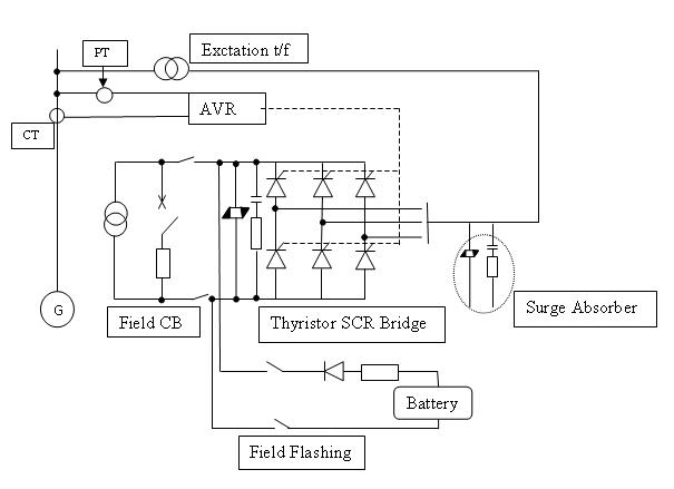
Excitation System
Excitation System provides field current to the rotor which produces the magnetic flux of the generator.
Main types of Exciters:
• Slip rings link the rotor’s field winding to an external dc source
• DC generator exciter(Shaft mounted)
• Brushless exciter
Input Power Source for Static Exciter
1. Self –excited shunt system
2. Self-excited compound system
3. Separately –excited station power source system
4. Separately-excited brushless generator system
The self-excited shunt system has been adopted in a great number of hydro power plants for its inexpensive cost and easy maintenance. Based on the studies, the static system is recommended as follows:
a. Input power source for static exciter is self-excited shunt system
b. Connection scheme of thyristor is applied to be the full bridge system
In case of self-excited shunt system is applied, an initial excitation power source must be separately provided to build-up the generator voltage up to a certain voltage at which AVR and thyristor gate circuits are adequately activated.